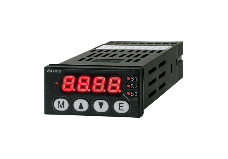
Small, Rapid Strain Gauge Panel Meter
VGM2A/B series
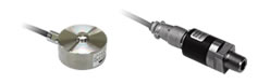
Use in combination with pressure sensors or load cells.
Industry's most compact body full of functions!!
All functions consolidated in a body of 48(W) × 24 (H) mm.
- Scaling function [Sets the values to be displayed for actual inputs as desired.]
- Zero shift function [Easy to adjust zero point]
- Auto AZ function [Sets the initial measurement as zero automatically.]
- Auto zero function [Measures from the last displayed value as "zero" (Tare)]
- Tracking zero function [Corrects slow zero-shift internally and automatically.]
- Auto peak hold function [Switches measurement to the peak hold mode automatically if the preset value is exceeded]
- Analog output function [Scales the analog output range as desired.]
- Level comparator function [Compares the level of measurements to output signals]
- Window comparator function [Compares the measurements between two windows (areas) to output signals.] * VGM2B only
- Control input chattering filter function [Filters chattering to prevent malfunction.]
- Key lock protection function [Prevents incorrect setting or malfunction due to inadvertent key operations.]
- Linearization function [Corrects the slope of the analog output or displayed value.] * VGM2A only
Level comparator function VGM2A: S1–S3, VGM2B: S1
Level comparison is made to measured values and the comparison result is
reflected to the S1–S3 output. Setpoint is set by the comparison setting(S1–S3 hereinafter, SET)
in comparison data. Hysteresis can be added to the comparison action by the hysteresis setting(HYS1–HYS3 hereinafter HYSS)
Window comparator function *VGM2B only
Window comparison is made to measured values and the comparison result is
reflected to the S2 output. The window high limit setpoint is set by the comparison
data high limit setpoint(SHI) The window low limit setpoint is set by the comparison data low limit setpoint(SLO)
Hysteresis can be added to the comparison action by the hysteresis setting(HYSW)
Linearizing correction function *VGM2A only
This function allows the slope of the analog output or displayed value for the sensor input to be corrected.
Measuring block Specifications
| Applicable sensor | Various strain gauge sensors (120Ω–1kΩ) |
|---|---|
| Sensor power supply | DC5V±10% 60mA |
| Measuring range | ±4mV/V |
| Span adjusting range | VGM2A: ±3.000mV/V |
| VGM2B: 0.001–3.000mV/V | |
| Zero adjusting range | ±1.000mV/V |
| Display setting range | ±9999 (Decimal point can be set to any position) |
| Minmum measuring sensitivity | 0.2µV/V/digit (Resolution of 1000 at span of 0.2mV/V and resolution of 9999 at span of 2.0mV/V) |
| A/D conversion | Consecutive comparison |
| Sampling speed | Can be freely set within range of 1–1000 times/sec |
| Filtering | Moving averaging (Can be freely set within range of OFF–256 times) |
| Accuracy (*1) | ±0.1%F.S.±1digit (23°C±5°C, and sampling speed of less than 20 times) ±0.15%F.S.±1digit (23°C±5°C, Standard) |
| Temperature characteristics | ± (0.005% of rdg+0.5digit)/°C |
| Display unit | 7-segment LED (Character height 7mm red) |
| Over range warming | Flashing at measuring limit point |
- *1 Take the accuracy of the selected pressure sensor or load cell into account.
Comparison block Specifications
| Control method | Computation by microcomputer |
|---|---|
| Comparison | VGM2A: 3-point MOS FET relay output (Level comparator 3-point (S1–S3)) |
| VGM2B: 2-point MOS FET relay output (Level comparator 1-point (S1), Window comparator 1-point (S2)) |
|
| S1 comparison condition | High limit/low limit evaluation is freely selectable |
| S2 comparison condition | VGM2A: High limit/low limit evaluation is freely selectable |
| VGM2B: GO/NG evaluation is freely selectable | |
| S3 comparison condition *VGM2A only | High limit/low limit evaluation is freely selectable |
| Setting range | ±9999 |
| Comparison cycle | Synchronizing with sampling period |
| Comparison output | Insulated the main ciruit by photocoupler (MOS FET relay AC/DC250V, 80mA) |
| Hysteresis | Can be freely set within range of 1–999digit for each setpoint |
| Response speed | 3msec. or less (1000 times/s, No filter) |
Data input/output specifications
| Output range | corresponding to displayed value changes (Free settbale within range) A3: 4–20mA, A4: 0–5V, A5: 0–10V |
|---|---|
| Output cycle | Synchronizing with sampling period |
| Load resistance | A3: 250Ω or less A4: 10kΩ or more A5: 10kΩ or more |
| Output accuracy | ±0.5%F.S. (23±5°C) (for displayed value) Temp. coefficient: ±200ppm/°C |
| Response speed | 3msec. or less (1000 times/s, No filter) |
| Resolution | A3: Approx. 45000 resolution to 4–20mA A4: Approx. 55000 resolution to 0–5V A5: Approx. 55000 resolution to 0–10V |
External control input specifications
| Electrical rating | "0" level: 0–1V, "1" level: 3–5V Input current: 5mA or less |
|---|
Other common specifications
| Functions | Tracking zero function, zero shift function, ect. |
|---|---|
| Memory backup | Using EEPRO (No. of write times guaranteed 1000,000 times 1 million) |
| Memory error warning | Memory check is cnducted every time power is turned on to display error if detected |
| Operating temperature | 0–50°C |
| Operating humidity | 35–85%RH (No condensation) |
| Power supply | DC24V±10% |
| Consuming current | 100mA (TYP) at 24V DC |
| Dielectric strength | For 1 min at 500VDC between power supply and other terminals |
| Insulation resistance | More than 100MΩ at 500 VD Cbetween power supply and other terminals |
| Accessories | Instruction manual, mounting bracket, packing, and engineering unit seal |
Model Selection

| Selection | Cheak | Model | Specifications | |
|---|---|---|---|---|
| 1.Model | VGM2A | 3 relay output advanced Small, Rapid Strain Gauge Panel Meter | ||
| VGM2B | 2 relay output advanced Small, Rapid Strain Gauge Panel Meter | |||
| 2.Comparison setting output | 3SO | VGM2A | 3-point MOS FET relay outpu (Level comparator 3-point (S1–S3)) |
|
| 2SO | VGM2B | 2-point MOS FET relay output (Level comparator 1-point (S1), Window comparator 1-point (S2)) |
||
| 3.Analog output specifications | A3 | Analog output 4–20mA | ||
| A4 | 0–5V output | |||
| A5 | 0–10V output | |||
| 4.Power supply | ○ | 4 | DC24V | |
Dimensions (Unit: mm)
Terminal connection
| VGM2A | VGM2B | ||||
|---|---|---|---|---|---|
| 1 | COM | Control output common (S1 S2) | 1 | COM | Control output common (S1 S2) |
| 2 | S1 | Control output S1 | 2 | S1 | Control output S1 |
| 3 | S2 | Control output S2 | 3 | S2 | Control output S2 |
| 4 | COM | Control input common (AZ PH CLR) | 4 | COM | Control input common (AZ CLR) |
| 5 | AZ | Control input AZ | 5 | AZ | Control input AZ |
| 6 | PH | Control input PH | 6 | NC | None |
| 7 | CLR | Control input CLR | 7 | CLR | Control input CLR |
| 8 | DC24− | Power input DC24V− | 8 | DC24− | Power input DC24V− |
| 9 | DC24V+ | Power input DC24V+ | 9 | DC24V+ | Power input DC24V+ |
| 10 | SensorsA | Sensor power supply +EXC | 10 | SensorsA | Sensor power supply+EXC |
| 11 | SensorsB | Sensors input −SIG | 11 | SensorsB | Sensors input −SIG |
| 12 | SensorsC | Sensor power supply −EXC | 12 | SensorsC | Sensor power supply −EXC |
| 13 | SensorsD | Sensors input +SIG | 13 | SensorsD | Sensors input+SIG |
| 14 | SensorsE | For shield wire of sensor cable | 14 | SensorsE | For shield wire of sensor cable |
| 15 | COM | Control output common (S3) | 15 | NC | None |
| 16 | S3 | Control output S3 | 16 | NC | None |
| 17 | AOUT− | Analog output − | 17 | AOUT− | Analog output − |
| 18 | AOUT+ | Analog output + | 18 | AOUT+ | Analog output + |