DIN48×96 Square type Digital(Pressure/Load) Meter
VPRH(V)-U series
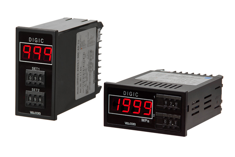
* Actual products may differ from photo depending on specifications.
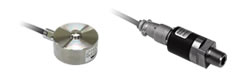
Use in combination with pressure sensors or load cells.
- Comparative setting outputs can be selected between relay and photo-MOS relay.
- Horizontal type (3 ½ digits) and vertical type (3 digits) are available in DIN sizes.
- 5 analog outputs can be selected.
- Power converter built in.
| Can be combined with sensors | Can be combined with all models of pressure sensors and load cells. |
|---|---|
| Sensor specifications | Refer to the pages of pressure sensors and load cells. |
| Calibration of amplifier and sensor | VPRH(V) amplifiers and pressure sensors or load cells have been calibrated as a pair. Amplifiers and sensors have been calibrated as a pair under the same serial number |
Specifications
| Display | 1999 3 1/2 Digit, 999 3Digit (vertical type) Red-color LED (character height 15mm) |
|---|---|
| Sampling rate | 4 times/sec (Standard) Can be set in the range of 1–10 times/sec (Refer to option spec.) |
| Accuracy | ±0.05%F.S.±1digit |
| Operating temperature | −10–55°C (No freezing) |
| Operating humidity | 0–90%RH (No condensation) |
| Dimensions | Horizontal type:48(W)×96(H)×127 (D: Protrusions not included) Vertical type:96(W)×48(H)×127 (D: Protrusions not included) |
| Weight | Approx. 400g (Varies with specification) |
| Accessories | Operating manual 1 copy (Specify English or Japanese.) Test report 1 copy (*1) |
- *1 Click here for accessories.
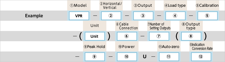
Model Selection
Pressure Sensor or Load Cell Selection
Click here for the specifications of pressure sensors, and click here for the loads cells
Specify the applicable models.
[e.g.] VPRV-A3-35.0MPaW-2S(HL)-1/VPRQ-35MPW (3m cable included)
| Selection | Cheak | Model | Specifications | |||
|---|---|---|---|---|---|---|
| 1.Model | ○ | VPR | DIN48×96 Square type Digital (Pressure/Load) Meter | |||
| 2.Horizontal/Vertical | H | Horizontal type panel mount | ||||
| V | Vertical type panel mount | |||||
| 3.Analog output | - | - | Output type | Response frequency | Load resistance | |
| D | Display only | |||||
| A1 | 1mV/digit | Approx. 10msec. (60% response) |
This value has been calculated as response frequency (= 1/2T (Hz)) based on the measured step response (0–100%) and rise time (T) with the sensor bridge resistance of 350Ω. Response frequency is determined by the sensor to be used. Consult with us when focusing on response. | 10kΩ or more (Output impedance 100Ω) | ||
| A2 | 1–5V | |||||
| A3 | 4–20mA | 250Ω or less | ||||
| A4 | 0–5V | 10kΩ or more (Output impedance 100Ω) | ||||
| A5 | 0–10V | |||||
| 4.Load type | Blank | Need not be specified when combining with a pressure sensor | ||||
| PS | To be specified only when combining with a load cell. | Compression | ||||
| PL | Tension | |||||
| PSL | Compression and tension *Add a "±" sign to the display range when using for tensile/compression load. |
|||||
| 5.Calibration | Example of calibration range | Pressure: 1.000MPa (0–1.000)MPa 500kPa (0–500)kPa ±100.0kPa (-100.0–100.0)kPa |
||||
| Load: 20.0kN (0–20.0)kN 100.0kN (0–100.0)kN ±1.00kN (-1.00–1.00)kN |
||||||
| 6.Cable connection | Blank | Specify the type of the connector for the pressure sensor to be combined. | Standard connector | |||
| W | Waterproof connector | |||||
| S | Pigtail | |||||
| 7.Number of setting outputs | - | - | Output type | Response frequency | Load resistance | |
| 0S | None | |||||
| 1S (*1) |
1-setting/Relay output type | Approx. 60msec. (63% response) |
AC250V 4A | |||
| 1SO | 1-setting/PhotoMOS relay output type | Approx. 50msec. (63% response) |
AC/DC250V 0.1A | |||
| 2S (*1) |
2-setting/Relay output type | Approx. 60msec. (63% response) |
AC250V 4A | |||
| 2SO | 2-setting/PhotoMOS relay output type | Approx.50msec. (63% response) |
AC/DC250V 0.1A | |||
| 1SA | 1-setting/Relay output type | Approx.3msec. (max.) |
AC125V 0.3A | |||
| 1SAO | 1-setting/Open collector output type | Approx.0.5msec. (max.) |
DC45V 0.15A | |||
| 2SA | 2-setting/Relay output type | Approx.3msec. (max.) |
AC125V 0.3A | |||
| 2SAO | 2-setting/Open collector output type | Approx.0.5msec. (max.) |
DC45V 0.15A | |||
| 8.Output type | H | When outputting 1 setting | Higher limit | *Always specify the output when placing an order | ||
| L | Lower limit | |||||
| HH | When outputting 2 setting | 1 setting=Higher limit 2 setting=Higher limit |
||||
| HL | 1 setting=Higher limit 2 setting=Lower limit |
|||||
| LH | 1 setting=Lower limit 2 setting=Higher limit |
|||||
| LL | 1 setting=Lower limit 2 setting=Lower limit |
|||||
| 9.Peak-holding (Optional) |
Blank | Without Peak-holding | ||||
| P | With Peak-holding *Not available if comparative setting output is0S | |||||
| 10.Power supply [Current consumpiton] | 1 | AC100V [2VA] | ||||
| 11 | AC110V [2VA] | |||||
| 2 | AC200V [2VA] | |||||
| 22 | AC220V [2VA] | |||||
| 4 | DC24V [100mA] | |||||
| 11.Auto-zeroing (Optional) |
Blank | Without Auto-zeroing | ||||
| Z | With Auto-zeroing *Not available if comparative setting output is0S | |||||
| 12.Indication conversion rate (Option) |
Indication Conversion Rate: standard4 times/sec Option( times/sec) *Specify in the range of 1–10 times/s. |
|||||
- *1 VPRH±100.0–±199.9 and VPRV±10.0–±99.9 can not be manufactured at the time of setting output: 1S/2
[Caution]
●When using an inductive load (relay, etc.) with a photoMOS relay output model, connect a diode to absorb surge.
Dimensions (Unit: mm)
Input/output Specifications
Sensor input Specifications
Peak-holding(Option)
Auto-zeroing(Option)
Digital Panel Meter