DIN48×96 Rapid Strain Gauge Panel Meter
VMM6 series
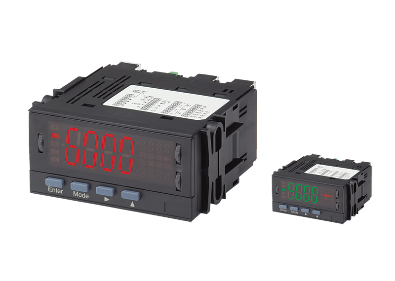
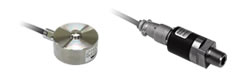
Use in combination with pressure sensors or load cells.
High-speed sampling at a maximum of 1000 samples per second
Easy to operate via the jog lever.
- Input range (−4 to 4mV) can be connected to pressure sensors and load cells.
- High speed sampling at a maximum of 1000 samples per second.
- Models with analog outputs are multiple output type that enables scaling at any range among 0 to 1 V, 0 to 10 V, 1 to 5 V, and 4 to 20 mA.
- Alarm setting values can be adjusted easily by the jog lever.
- LED alternates between red and green, allowing the judgment result to be identified by color.
- Comparative setting outputs (3 points: H/G/L) included as standard.
- Various functions included as standard.
"Start hold", "Digital zero", "Peak hold" and "Pattern select" functions included.
Various Functions
Pattern Select Function
This function stores up to eight patterns of scaling data and comparator data, and allows the users to set patterns as desired.
Pattern selection can be controlled either via terminals or via front keys according to the condition data setting. In case of control via terminals, short the terminals between P.SEL1 to 3 and COM or make them equipotential to enable pattern switching from P-1 up to P-8. In case of control via front keys, hold down the increment key for approx. 3 seconds to switch patterns.
Start Hold Function
This function holds the display at the desired timing. Either A or B type can be set according to the condition data.
A type is a free run mode. In the free run condition, shorting S/H and COM terminals or making them equipotential will hold the displayed value and the comparison judgment value.
B type is a one-shot mode. In the hold condition, shorting S/H and COM terminals or making them equipotential will output the displayed value and the comparison judgment value once.
Peak Hold Function
This function holds any of the maximum (peak) value, the minimum (valley) value, and the difference between the maximum and the minimum (peak – valley) and outputs the value held. (The value to be held is switched according to the condition data.)
Shorting S/H and COM terminals or making them equipotential will turn ON the peak hold function.
Digital Zero Function (Display reset function)
This function forcibly zeros the displayed value. It is useful when subtracting tare weight during load measurement with load cells connected.
Display reset (Digital zero) function ON/OFF can be controlled via terminals or via front keys according to the condition data setting.
In case of control via terminals, shorting the terminals between DZ and COM or make them equipotential to turn ON the display reset function. In case of control via front keys, hold down the shift key for approx. 3 seconds to turn ON the function.
Specifications
| Display | Main display: Red/green 7-segment display (character height: approx. 20mm) Sub display: Red 7-segemnt display (character height: approx. 6mm) |
|---|---|
| Display range | −9999 to 9999 |
| Operating temperature ranges | 0 to 50°C |
| Operating humidity ranges | 35 to 85%RH |
| Storage temperature ranges | −10 to 70°C |
| Storage humidity ranges | 60%RH or less |
| Power supply | AC power unit: 100 to 240V AC ±10% DC power: 12V to 48V DC ±10% |
| Power consumption | AC ps Maximum load: approx. 8VA at 100 VAC DC ps Maximum load: approx. 7W at 24 VDC |
| Withstand voltage | AC PS PS-input, output: 1,500 VAC, 1minute (AC PS) |
| DC PS PS-input, output: 1,500 VDC, 1minute (DC PS) |
|
| (common) Input-Output: 500 VDC, 1minute Output-Output: 500 VDC, 1minute Case-PS, input, output: 1,500 VAC, 1minute |
|
| Insulation resistance | Among the above terminals: 500 VDC 100MΩ or more |
| Outer demensions | 96mm(W)×48mm(H)×99.5mm(D) |
| Weight | Approx. 450g |
| Accessories | Instruction Manual×1 Unit indication label×1 Mounting band×2 6-P terminal cover×3 |
Strain Gauge input specifications
| Zero adjustment range | ±1mV/V |
|---|---|
| Span adjustment range | 1–3mV/V |
| Maximum Resolution | Sensor Power Supply 5V: 0.5µV/digit Sensor Power Supply 10V: 1µV/digit |
| Accuracy (*1) | ± (0.1% of F.S+2digit) (23°C±5°C 35–85%) |
| Sampling rate | 1000 times/sec |
| Sensor Power Supply | 5V±5% 60mA 10V±5% 60mA |
- Accuracy applies when the sampling rate is 20 samples/s or less.
- 1) Take the accuracy of the selected pressure sensor or load cell into account.
Comparator Output Specifications
| Judgment value setting range | −9999 to 9999 | ||
|---|---|---|---|
| Hystersis | Settable in the range of 1 to 999 digits with respect to each judgment value | ||
| Comparison action | Depending on sampling rate | ||
| Comparator relay | Relay contact output | Maximum 10ms | |
| Number of contacts | Relay contact×3 | ||
| Contact rating | AC250V 2A (resistive load) DC30V 2A (resistive load) |
||
| Comparison conditions | indicated value > high limit judgment value | Judgment:HI | |
| low limit judgment value ≤ indicated value ≤ high limit judgment value | Judgment: GO | ||
| low limit judgment value > indicated value | Judgment: LO | ||
| Photocoupler output | Output quantity | Photocoupler ×3 | |
| Photocoupler output | 200µs | ||
| Contact rating | 30V DC 20mA (resistive load) | ||
| Comparison conditions | indicated value > high limit judgment value | HI | |
| high limit judgment value ≥ indicated value ≥ low limit judgment value | GO | ||
| low limit judgment value > indicated value | LO | ||
Analog Output Specifications
| Resistive Load | 0 to 1V, 0 to 10V, 1 to 5V: 10kΩ or more 4 to 20mA: 550Ω or less |
|---|---|
| Accuracy | ±(0.5% of F.S.) |
| Ripple | 0 to 1V, 0 to 10V, 1 to 5V: ±50mVpp 4 to 20mA: ±25mVpp |
| Conversion method | PWM conversion |
| Resolution | Equivalent to 14 bits |
| Scaling | Digital scaling |
| Response rate | Approx. 0.5 seconds |
BCD Output Specifications
| Output type | open collector or TTL-compatible |
|---|---|
| Polarity | The applicable transistor (open collector) or polarity bit (TTL) turns on when negative values are indicated |
| Output rating | DC30V MAX 10mA MAX |
Model Selection

| Selection | Check | Model | Specifications | |
|---|---|---|---|---|
| 1.Model | ○ | VMM6 | DIN48×96 Rapid Strain Gauge Panel Meter | |
| 2.Comparison Setting Output | - | - | No. of settings | Output type |
| 2S | 2-point (H/G/L) | Relay signal×3 AC250V 2A (Load resistance) DC30V 2A (Load resistance) |
||
| 2SO | 2-point(H/G/L) | Photo-coupler×3 DC30V 2mA (Load resistance) | ||
| 3.Output | D | None | ||
| A | Can be switched among four types: 0–1V or 0–10V or 1–5V or 4–20mA (with scaling function) | |||
| B4 | BCD output (Open collector output NPN type) | |||
| 4.Input Signal | ○ | GV | Strain Gauge input (350Ω) (Zero adjustment range ±1mV/V, Span adjustment range 1–3mV/V, Measuring range: -4–4mV/V) |
|
| 5.Power | 7 | AC100–240V (±10%) | ||
| 8 | DC12–48V (±10%) | |||
Dimensions (Unit: mm)
Connection diagram of I/O screw terminal
External control terminals
| Internal circuit | Pull-up at approx. 5V (Resistance value: Approx. 10kΩ) |
|---|---|
| Control signal HI | 4.2–5V for the level COM terminal |
| Control signal LO | 0–0.4V for the level COM terminal |
| Start hold | A type: Shorting the S/H and COM terminals or making them equipotential will hold the display value. B type: Shorting the S/H and COM terminals or making them equipotential will output the display value. |
| Digital zero | Shorting the DZ and COM terminals or making them equipotential will turn ON the digital zero function. |
| Peak hold | Shorting the PH and COM terminals or making them equipotential will turn ON the peak hold function. |
| Relay reset | Shorting the R.RESET and COM terminals or making them equipotential will turn ON the relay reset function. |
| Pattern 1 | Pattern 2 | Pattern 3 | Pattern 4 | Pattern 5 | Pattern 6 | Pattern 7 | Pattern 8 | |
|---|---|---|---|---|---|---|---|---|
| P.SEL0 | OFF | ON | OFF | ON | OFF | ON | OFF | ON |
| P.SEL1 | OFF | OFF | ON | ON | OFF | OFF | ON | ON |
| P.SEL2 | OFF | OFF | OFF | OFF | ON | ON | ON | ON |
- ON: Short-circiut and COM terminals or making them equipotential.
- OFF: Release the S/H and COM terminals or 5V.