Digital Panel Meter VALCOR series
F4/F5 series
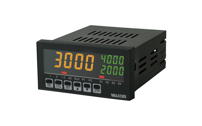
Extraordinary performance in the fields of coating and wastewater.
F4/F5 shows differential pressure between two input channels on the main display.
Various setting outputs make it more useful.
- Current operation state (normal/abnormal) can be found easily by the color of the value (on main display).
- Measured values can be displayed in 3 colors: red, orange and green, as desired, in areas partitioned by set values.
- High speed sampling as fast as 1000 samples per second.
- Fast output enables use for high-speed and safe control purposes.
- Analog output ranges of 4 to 20 mA, 1 to 5 V and 0 to 5 V included as standard.
- Output scaling function included, which allows the measurement range to be set variable as desired.
Specifications
| Input signal | Process input: 4–20mA/0–5V/1–5V/0–10V Selectable Power supply for sensor: DC12V 80mA max. |
|---|---|
| Input impedance | 4–20mA: 68Ω 0–5V/1–5V/0–10V: 68kΩ |
| Display | −9999–9999 (User selectable decimal places) 4-digit LCD with 3 changeable colors (red, orange and green) |
| Sampling cycle | 1000 times/sec max. |
| Display renewal rate | 1–10 times/sec Selectable |
| Accuracy | Display: ± 0.05%F.S.±1digit (25°C±3°C) Analog output: ±0.5%F.S. (25°C±3°C) |
| Analog output | 4–20mA/0–5V/1–5V Range to be switched. Option 0–10V(*1) |
| Setting output (Select by model) |
4-setting Relay output AC125V 0.3A (per 1 setting)/DC24V 1A (per 1 setting) Response time 6msec. or less (*1) 4-setting Photomos Relay output AC/DC250V 0.1A (per 1 setting) Response time 5msec. or less (*1) |
| Operating temperature range | 0–55°C (No freezing) |
| Operating humidity range | 35–85%RH (No condensation) |
| Power supply (Select by model) |
AC90–240V 50/60Hz Current consumpiton 15VA or less |
| DC24V ±10% Current consumpiton 300mA or less | |
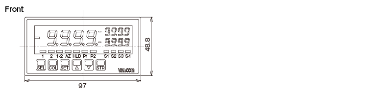
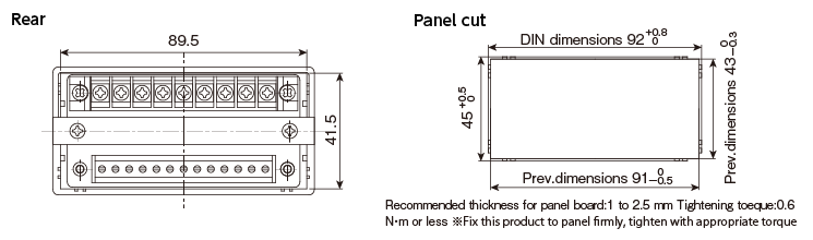
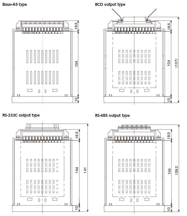
| Dimensions | 97(W)×48.8(H)×132.5(D) *Option terminals are not described in the following figure |
| Weight | Approx. 300g (Varies with specification) |
| Accessories | Operation manual (1 copy), Unit labels, List of initial settings, Panel mounting bracket, Amphenol connector (5730240) (BCD output function only) |
| Other Functions | Display scaling, Analog output scaling, Display hold (upper peak / bottom peak / transition peak / peak-to-peak / sample hold), Auto-zero, Max./min. value indication, Pattern selection, Simulation, Input value shift sub-display ON/OFF, Key protection, Main display color change, Display update rate setting, Power-saving mode ON/OFF, Sampling rate setting, Dumping time constant, Zero suppress ON/OFF, Fix-zero |
- (*1)0–90% of response time. Sampling cycle, damping time constant at high-speed setting
Setting output
| F4 | 4-setting output to ch. (1-2) |
|---|---|
| F5 | 2-setting output to ch.1 2-setting output to ch. (1-2) |
Option output
| A5 Analog output (0–10V) |
0–10V Safe load resistance 10kΩ or more Response time 4msec.or less (*) Analog output accuracy ±0.5%F.S. (25°C±3°C) Temperature characteristics ±0.35%F.S./10°C |
|---|---|
| BO BCD open collector output |
NPN open collector DC50V 100mA or less Response time 5msec. or less (*) |
| RS RS-232C |
RS-232C-compliant 2-wire half-duplex Asynchronous Communication rate (300/600 1200/2400/4800/9600/19200/38400 bps) Stop bit (1, 2bit) Parity (NON/ODD/EVEN) Data length (7, 8bit) Unit No. (0–99) |
| R1 RS-485 |
RS-485-compliant 2-wire half-duplex Asynchronous Communication rate (300/600 1200/2400/4800/9600/19200/38400 bps) Stop bit (1, 2bit) Parity (NON/ODD/EVEN) Data length (7, 8bit) Unit No. (0–99) |
- (*)0–90% of response time. Sampling cycle, damping time constant at high-speed setting
Model Selection

| Selection | Cheak | Model | Specifications |
|---|---|---|---|
| 1.Model | F4 | Differenital pressure calculating main display switch-type (Can be switched among ch.1, ch.2 and ch. (1-2) with the [SEL] key) |
|
| F5 | MDifferenital pressure calculating main display switch-type (Can be switched among ch.1, ch.2 and ch. (1-2) with the [SEL] key) |
||
| 2.Power supply [Current consumpiton] | 4 | DC 24V ±10% Current consumpiton 300mA or less | |
| 7 | AC 90–240V Current consumpiton 50/60Hz 15VA or less | ||
| 3.Input signal | N | Multiple-input Process input 4–20mA/0–5V/1–5V Power supply for sensor DC12V 80mA max. |
|
| A5 | 0–10V/4–20mA (Note) | ||
| 4.Setting output | S | 4-setting Relay output AC125V 0.3A/DC24V 1A (per 1 setting) | |
| O | 4-setting Photomos Relay output AC/DC250V 0.1A (per 1 setting) | ||
| 5.Output signal (Option) |
Blank | 4–20mA Safe load resistance: 250Ω or less 0–5V/1–5V Safe load resistance: 10kΩ or more Analog output accuracy ±0.5%F.S. (25°C±3°C) Temperature characteristics ±0.35%F.S./10°C |
|
| A5 | Analog output 0–10V Safe load resistance: 10kΩ or more | ||
| BO | BCD open collector output NPN type | ||
| RS | RS-232C | ||
| R1 | RS-485 |
- (Note) Do not use sensor power supply of this unit when connecting pressure transducer (VALCOM product),
sensor 0–10V output type (Model code:A5). Please prepare sensor power supply separately.
Dimensions (Unit: mm)
F4/F5 Process input type
Terminal connection

(A)Terminals for control Output, terminals for control input (upper) connection
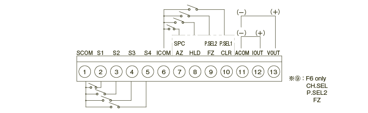
| Terminal No. | Name | Functions | Terminal No. | Name | Functions |
|---|---|---|---|---|---|
| 1 | SCOM | COM terminal of comparison setting output | 8 | HLD | Hold |
| 2 | S1 | Comparison setting output 1 terminal | 9 | P.SEL2 | Pattern SEL 2 |
| 3 | S2 | Comparison setting output 2 terminal | FZ | Forced zero | |
| 4 | S3 | Comparison setting output 3 terminal | 10 | P.SEL1 | Pattern SEL 1 |
| 5 | S4 | Comparison setting output 4 terminal | CLR | Clear | |
| 6 | ICOM | COM terminal of control | 11 | ACOM | Analog output COM |
| 7 | SPC | Sample hold clear | 12 | IOUT | Analog (Current) Output+ |
| AZ | Auto-zero | 13 | VOUT | Analog (Current) Output+ |
(B)Option output connection
●BCD signal output

Amphenol: 5740240 Accessories: Amphenol: 5730240
| Item | Pin No. | Item | |||
|---|---|---|---|---|---|
| EOC (Signal of over the conversion) | 1 | 13 | Digital GND. | ||
| ×100 BCD OUT |
1 | 2 | 14 | 1 | ×102 BCD OUT |
| 2 | 3 | 15 | 2 | ||
| 4 | 4 | 16 | 4 | ||
| 8 | 5 | 17 | 8 | ||
| ×101 BCD OUT |
1 | 6 | 18 | 1 | ×103 BCD OUT |
| 2 | 7 | 19 | 2 | ||
| 4 | 8 | 20 | 4 | ||
| 8 | 9 | 21 | 8 | ||
| - | 10 | 22 | - | ||
| OVER (Over) | 11 | 23 | POL. (Polarity) | ||
| - | 12 | 24 | - | ||
●RS-232C communication

| Name | Pin No. | Functions | Input output |
|---|---|---|---|
| SD | 2 | Transmit data | output |
| RD | 3 | Received data | Input |
| FG | 1 | Frame ground, or cable shield | - |
| RS | 4 | Request to send | output |
| CS | 5 | clear to send | Input |
| SG | 7 | Signal ground | - |
| DR | 6 | Data set ready | Input |
| ER | 20 | Data terminal ready | output |
●RS-485 communication

| Signal name | Terminal No. | Item | Input output |
|---|---|---|---|
| A+ | 23 | Non inverting output | Input output |
| B- | 24 | Inverting output | Input output |
| SG | 25 | Signal ground | - |
| Terminator | 26 | Terminals are short-circuited |
- |
| 27 |
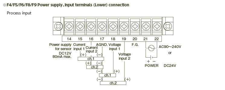
(C)Input/output terminals connection
Digital Panel Meter