DIN48×96 Digital Color Panel Meter
VW2 series
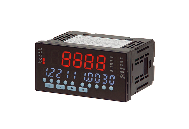
User-friendly touch switches allow setting to be made digit by digit!
High-intensity LEDs produce pure color tones.
Setting values shown in white can be easier to discriminate from other values.
- Multiple process inputs: 1 to 5V, ±5V, ±10V, 4 to 20mA, ±20mA
- User-selectable between 12V DC, 100mA and 24V DC, 50mA
- Models with analog outputs are multiple output type: 0to 2V, 0 to 10V, ±10V, 1 to 5V, 0 to 20mA, 4 to 20mA
- High-brightness LEDs are fully adopted. Main display color changes between green and red. Judgment results can be distinguished by color.
Sub display shows values in white (different from main display), which doubles legibility. - CE-certified.
- Alarm setting: 2 contacts (3 relay outputs or photo-coupler output) or 4 contacts (5 relay outputs or photo-coupler output)
- Pattern select function included (Up to eight patterns)
- Peak hold functions
"sample hold", "Peak hold", "Bottom hold" and "peak-to-peak" functions included. - Various functions
"Leading zero suppress", "Forced-zero" and "Reelay reset" functions included.
Specifications
| Input Method | Single-end |
|---|---|
| A/D Conversion Method | ΔΣconversion method |
| Sampling Rate | MAX. 250 times/sec. |
| Display | Main display: Red/Green 7 segments LED display (Character height: Approx. 14.9mm) Sub display: White 7 segments LED display(Character height: Approx. 9mm) |
| Polarity Display | Displayed automatically for negative results. |
| Display Range | −19999–99999 |
| Zero Display | Leading zero suppress |
| Outer Control | 4 out of the following 5 functions are assigned to the external control terminals. *If the pattern select function is included, the remaining terminals available for other functions will be limited. 2 more functions (if 4 patterns used) or 1 more function (if 8 patterns used) ①Pattern select ②Hold ③Peak hold / Bottom hold / Peak to peak (Difference between the peak and the bottom) ④Forced-zero ⑤Relay reset |
| Range of Use Temperature | −5–50°C |
| Range of Use Humidity | 35–85%RH (No condensation) |
| Storage Temperature Range | −10–70°C |
| Storage Humidity Range | 60%RH or less |
| Power | AC100–240V±10% 50/60Hz |
| Power Consumption | AC100V: 12VA max. AC240V: 15VA max. |
| Sensor Power Supply | Possible to switch from DC12V 100mA or DC24V 50mA setting |
| External dimensions | 96mm(W)×48mm(H)×99.7mm(D) |
| Weight | Approx. 250g |
| Dielectric Strength | Between Power terminal and Input terminal/External control terminals/Analog output AC2000V for 1 minute |
| Between Power terminal and Comparative output AC1500V for 1 minute | |
| Between Input terminal and External control terminals/Analog output/Comparative output AC1500V for 1 minute | |
| Between Case and Terminal AC2000V for 1 minute | |
| Insulation Resistance | 100MΩ min. at 500V DC between above terminals |
| IP Rating | IP66 (Front) |
| Case (Material/Color) | Polycarbonate/Black UL94V-0 |
| Overrange Display | OVER or -OVER for any input signal outside the display range. "OVER" or "-OVER" is displayed if input exceeds the measurement range by more than ±10% |
| Decimal Point | Can be set at any desired place. |
Process signal input specifications
| Measuring Range | 1–5V, ±5V, ±10V, 4–20mA, ±20mA |
|---|---|
| Display | Offset: -19999–99999 Full scale: -19999–99999, Resolution: ±19999 |
| Input Impedance | Approx. 1MΩ: (1–5V, ±5V, ±10V) Approx. 10Ω: (4–20mA, ±20mA) |
| Maximum Safe Input | ±100V: (1–5V, ±5V, ±10V) ±50mA: (4–20mA, ±20mA) |
| Accuracy * | ± (0.1% of FS +1digit) (At the time of 23°C±5°C 35–85%RH) |
- (*) Accuracy applies when the sampling rate is 60 samples/s or less.
Comparison output specifications
| Control Method | Microcomputer-based | ||
|---|---|---|---|
| Trigger Value Range | -19999–99999 | ||
| Hysteresis | Can be set in the range of 1–9999 digits for each value. | ||
| Comparison Operation | Depends on the sampling rate. | ||
| Setting Condition | 2-setting output type VW27N-2S□ VW27N-2SO□ |
H. G. L. AL1 judgment value>AL2 judgment value (GO) >AL3 judgment value |
|
| Comparison Condition | Judgment | ||
| Displayed value>AL1 judgment value | AL1: ON | ||
| AL1 judgment value≥Displayed value≥AL3 judgment value | AL2: ON | ||
| AL3 judgment value>Displayed value | AL3: ON | ||
| G. L. L. AL1 judgment value (GO) >AL2 judgment value>AL3 judgment value |
|||
| Comparison Condition | Judgment | ||
| Displayed value≥AL2 judgment value | AL1: ON | ||
| AL2 judgment value>Displayed value≥AL3 judgment value | AL2: ON | ||
| AL3 judgment value>Displayed value | AL3: ON | ||
| H. H. G. AL1 judgment value>AL2 judgment value>AL3 judgment value (GO) |
|||
| Comparison Condition | Judgment | ||
| Displayed value>AL1 judgment value | AL1, AL2: ON | ||
| AL1 judgment value≥Displayed value>AL2 judgment value | AL2: ON | ||
| AL2 judgment value≥Displayed value | AL3: ON | ||
| 4-setting output type VW27N-4S□ VW27N-4SO□ |
H.H.H.H.G. AL1 judgment value>AL2 judgment value>AL3 judgment value>AL4 judgment value>AL5 judgment value (GO) |
||
| Comparison Condition | Judgment | ||
| Displayed value>AL1 judgment value | AL1,AL2,AL3,AL,4 | ||
| AL1 judgment value≥Displayed value>AL2 judgment value | AL2,AL3,AL4 | ||
| AL2 judgment value≥Displayed value>AL3 judgment value | AL3,AL4 | ||
| AL3 judgment value≥Displayed value>AL4 judgment value | AL4 | ||
| AL4 judgment value≥Displayed value | AL5 | ||
| H.H.H.G.L. AL1 judgment value>AL2 judgment value>AL3 judgment value>AL4 judgment value(GO)>AL5 judgment value |
|||
| Comparison Condition | Judgment | ||
| Displayed value>AL1 judgment value | AL1,AL2,AL3 | ||
| AL1 judgment value≥Displayed value>AL2 judgment value | AL2,AL3 | ||
| AL2 judgment value≥Displayed value>AL3 judgment value | AL3 | ||
| AL3 judgment value≥Displayed value≥AL5 judgment value | AL4 | ||
| AL5 judgment value>Displayed value | AL5 | ||
| H.H.G.L.L. AL1 judgment value>AL2 judgment value>AL3 judgment value(GO)>AL4 judgment value>AL5 judgment value |
|||
| Comparison Condition | Judgment | ||
| Displayed value>AL1 judgment value | AL1,AL2 | ||
| AL1 judgment value≥Displayed value>AL2 judgment value | AL2 | ||
| AL2 judgment value≥Displayed value≥AL4 judgment value | AL3 | ||
| AL4 judgment value>Displayed value≥AL5 judgment value | AL4 | ||
| AL5 judgment value>Displayed value | AL4,AL5 | ||
| H.G.L.L.L. AL1 judgment value>AL2 judgment value (GO) >AL3 judgment value>AL4 judgment value>AL5 judgment value |
|||
| Comparison Condition | Judgment | ||
| Displayed value>AL1 judgment value | AL1 | ||
| AL1 judgment value≥Displayed value≥AL3 judgment value | AL2 | ||
| AL3 judgment value>Displayed value≥AL4 judgment value | AL3 | ||
| AL4 judgment value>Displayed value≥AL5 judgment value | AL3,AL4 | ||
| AL5 judgment value>Displayed value | AL3,AL4,AL5 | ||
| Comparison Relay | Contact Rating | AC125V 0.3A (Resistive load) DC30V 1A (Resistive load) |
|
| Number of Contacts | Relay contact×3 (VW27N-2S□) or Relay contact×5(VW27N-4□) |
||
| Minimum Applicable Load | 10µA 10mV DC | ||
| Mechanical Lifespan | More than 50 million times | ||
| Electrical Lifespan | More than hundred thousand times (Resistive load) | ||
| Photo-coupler Output Open Collector Output (NPN) |
Output Constant | Sink current: 50mA MAX. | |
| Applied voltage | 30V MAX. | ||
| Output saturation voltage | 50mA 1.2V or less | ||
| Number of Outputs | Photo-coupler Output (NPN) ×3 (VW27N-2SO□) or Photo-coupler Output (NPN) ×5 (VW27N-4O□) |
||
| Comparison Warning Function | Normal judgment output, zone judgment output, tolerance judgment output | ||
| Comparison Condition Memory | 8 patterns are memorized. | ||
Analog output specifications
| Load Resistance | 0–2V, 0–10V, -10–10V, 1–5V:10kΩ or more 0–20mA, 4–20mA:550Ω or more |
|---|---|
| Accuracy | ± (0.1% of FS) |
| Ripple | 0–2V, 0–10V, -10–10V, 1–5V:±50mVp-p 0–20mA, 4–20mA:±25mVp-p |
| Conversion Method | D/A conversion method |
| Resolution | Equivalent to 15bit (Depends on the scaling setting) |
| Scaling | Digital scaling |
| Response Speed | 10ms or less 0→90% Responsed (Sampling rate: 250 times/sec.) *Response speed 2ms±2 (1/Sampling rate) ms or less |
- (*) Ripple voltages are vales output when load resistance is 250Ω and current output is 20mA.
Model Selection

| Selection | Check | Model | Specifications | |
|---|---|---|---|---|
| 1.Model | ○ | VW2 | DIN48×96 Digital Color Panel Meter | |
| 2.Power | ○ | 7 | AC100–240V (±10%) 50/60Hz | |
| 3.Input Signal | ○ | N | Select from prosess input (1–5V, ±5V, ±10V, 4–20mA, ±20mA) | |
| 4.Comparison Setting Output | - | - | Output type | |
| 2S | Relay signal×3 AC125V 0.3A (Resistive load) DC30V 1A(Resistive load) |
|||
| 2SO | Photo-coupler ×3 Sink current 50mA MAX. Applied voltage 30V MAX. |
|||
| 4S | Relay signal×5 AC125V 0.3A (Resistive load) DC30V 1A (Resistive load) |
|||
| 4SO | Photo-coupler ×5 Sink current 50mA MAX. Applied voltage 30V MAX. |
|||
| 5.Output | D | Exclusive use of the indication | ||
| A | With analog output | |||
- (*)4S/4SO relay signal × 5 (Can be set as option.) Contact your nearest sales office for details.
External dimensions (Unit: mm)
Panel cut dimensions(Unit: mm)
Input/output terminal
Transition diagram
Applicable crimp terminal

Digital Panel Meter