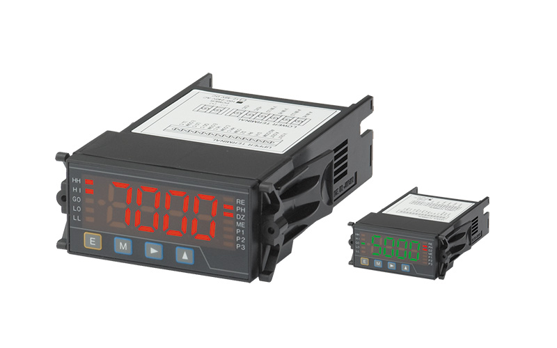
DIN36×72 Rapid Digital Panel Meter
VMM7 series
Compact design and multi-input support high speed at a maximum of 1000 samples per second.
Alternating green and red LED intuitively understandable for users.
- Multiple process inputs: 1 to 5V, ±5V, 4 to 20mA, and ±20mA
- High speed sampling at a maximum of 1000 samples per second.
- Models with analog outputs are multiple output type that enables scaling at any range among 0 to 1 V, 0 to 10 V, 1 to 5 V, and 4 to 20 mA.
- CE-compliant (* Supply voltage, DC drive only)
- Compact design of 72 (W) × 36 (H) mm (DIN standard) and space-saving, with an easy-to-read large monitor of 16 mm in character height.
- LED alternates between red and green, allowing the judgment result to be identified by color.
- Five comparison setting outputs and various functions included as standard.
"Start hold", "Digital zero", "Peak hold" and "Pattern select" functions included.
Various Functions
Pattern Select Function
This function stores up to eight patterns of scaling data and comparator data, and allows the users to set patterns as desired.
Pattern selection can be controlled either via terminals or via front keys according to the condition data setting. In case of control via terminals, short the terminals between P.SEL1 to 3 and COM or make them equipotential to enable pattern switching from P-1 up to P-8. In case of control via front keys, hold down the increment key for approx. 3 seconds to switch patterns.
Start Hold Function
This function holds the display at the desired timing. Either A or B type can be set according to the condition data.
A type is a free run mode. In the free run condition, shorting S/H and COM terminals or making them equipotential will hold the displayed value and the comparison judgment value.
B type is a one-shot mode. In the hold condition, shorting S/H and COM terminals or making them equipotential will output the displayed value and the comparison judgment value once.
Peak Hold Function
This function holds any of the maximum (peak) value, the minimum (valley) value, and the difference between the maximum and the minimum (peak – valley) and outputs the value held. (The value to be held is switched according to the condition data.)
Shorting S/H and COM terminals or making them equipotential will turn ON the peak hold function.
Digital Zero Function (Display reset function)
This function forcibly zeros the displayed value. It is useful when subtracting tare weight during load measurement with load cells connected.
Display reset (Digital zero) function ON/OFF can be controlled via terminals or via front keys according to the condition data setting.
In case of control via terminals, shorting the terminals between DZ and COM or make them equipotential to turn ON the display reset function. In case of control via front keys, hold down the shift key for approx. 3 seconds to turn ON the function.
Specifications
| Display | 7-segment LED display (character height: approx. 16mm) |
|---|---|
| Polarity display | Automatically indicated when the calculation result is negative |
| Display range | −9999 to 9999 |
| Overrange warning | "OVER" or "-OVER" indication in response to an input signal exceeding the display range |
| Decimal point | Settable to any digit position |
| Zero indication | Leading zero suppression |
| External control | P.SEL1–3, HOLD, PH, DZ (depending on output units) |
| Operating temperature ranges | 0 to 50°C |
| Operating humidity ranges | 35 to 85%RH (no condensation) |
| Storage temperature ranges | −10 to 70°C |
| Storage humidity ranges | 60%RH or less |
| Power supply | AC power unit: 100 to 240V AC ±10%, DC power: 12V to 48V DC ±10% |
| Power consumption | 8VA max. (AC power unit) 7W max. (DC power unit) |
| Withstand voltage | AC power: Power terminal to input terminal, COM, comparison output, BCD, analog output, or RS communications terminal 1500 V AC for 1 minute |
| DC power: Power terminal to input terminal, COM, comparison output, BCD, analog output, or RS communications terminal 500 V DC for 1 minute |
|
| (common): Input terminal to comparison output, BCD, analog output, or RS- communications terminal 500 V DC for 1 minute |
|
| Insulation resistance | 500 V DC at 100MΩ or more between the noted terminals |
| Outer demensions | 72mm(W)×36mm(H)×118mm(D) |
| Weight | Approx. 160g |
| Accessories | Instruction Manual×1 |
Process signal input specifications
| Measurement Range | Range 1V: 1 to 5V, Range 2V: ±5V Range 2A: 4 to 20mA, Range 3A: ±20mA |
|---|---|
| Display | Offset: ±9999 Ful scale: ±9999 |
| Input Impedance | Range 1V, Range 2V: Approx. 1MΩ Range 2A, Range 3A: Approx.10Ω |
| Max. Allowable Input | Range 1V, Range 2V: ±100V Range 2A, Range 3A: ±50mA |
| Accuracy | Range 1V, Range 2V:±(0.03% of rdg +2digit) (23°C±5°C 35–85%) Range 2A, Range 3A:±(0.1% of rdg +3digit) (23°C±5°C 35–85%) |
| Sensor Power Supply | DC24V±10% 25mA, or DC12V±10% 25mA |
| Sampling rate | 1000 times/sec |
- (*) Error applies if the sampling rate is 20 times/sec or less
Comparator Output Specifications
| Control method | Microcomputer-based calculation method | |
|---|---|---|
| Judgment value setting range | −9999 to 9999 | |
| Hystersis | Settable in the range of 1 to 999 digits with respect to each judgment value | |
| Comparison action | Depending on sampling rate | |
| Comparison conditions | indicated value > High-high limit judgment value > high limit judgment value | Judgment: HH, HI |
| High-high limit judgment value ≥ indicated value > high limit judgment value | Judgment: HI | |
| high limit judgment value ≥ indicated value ≥ low limit judgment value | Judgment: GO | |
| low limit judgment value > indicated value ≥ low-low limit judgment value | Judgment: LO | |
| low limit judgment value > low-low limit judgment value > indicated value | Judgment: LO, LL | |
| Setting conditions | High-high limit judgment value > high limit judgment value > low limit judgment value > low-low limit judgment value | |
| Comparator relay | Number of contacts | Relay contact ×5 |
| Contact rating | 125V AC, 0.3A (resistive load) 30V DC, 1A (resistive load) |
|
| Mechanical life | 50 million times or more | |
| Electrical life | 100,000 times or more (resistive load) | |
| Photocoupler output | Output quantity | Photocoupler ×5 |
| Output rating | Sink current 50 mA MAX. Voltage applied: 30V MAX. Output saturation voltage 1.2V or less at 50 mA |
|
Analog Output Specifications
| Resistive Load | 0 to 1V, 0 to 10V, 1 to 5V:10kΩ or more 4 to 20mA: 550Ω or less |
|---|---|
| Accuracy | ±(0.5% of FS) |
| Ripple | 0 to 1V, 0 to 10V, 1 to 5V: ±50mVpp 4 to 20mA: ±25mVpp |
| Conversion method | PWM conversion |
| Resolution | 13 bits or equivalent |
| Scaling | Digital scaling |
| Response rate | Approx. 0.5 seconds |
RS-232C Output Specifications
| Synchronous System | Start-stop transmission system |
|---|---|
| Communication System | Full duplex |
| Transmission Rate | 38.4k to 2.4k bps |
| Star bit | 1bit |
| Data Length | 7bit/8bit |
| Parity | Even parity/odd parity/none |
| Stop bit | 1bit/2bit |
| Character Code | ASCⅡcodes |
| Signal Name in Use | TXD, RXD, SG |
| Number of Units Connected | 1 |
| Line Length | 15m |
| Delimiter | CR+LF/CR |
RS-485 Output Specifications
| Synchronous System | Start-stop transmission system |
|---|---|
| Communication System | Two-line semi-duplex (polling selecting system) |
| Transmission Rate | 38.4k to 2.4k bps |
| Star bit | 1bit |
| Data Length | 7bit/8bit |
| Parity | Even parity/odd parity/none |
| Error Detection | BCC (block check character) checksum |
| Stop bit | 1bit/2bit |
| Character Code | ASCⅡcodes |
| Signal Name in Use | Non-inverse (+), inverse(−) |
| Number of Units Connected | A maximum of 31 meters |
| Line Length | 500m maximum |
| Delimiter | CR+LF/CR |
Model Selection

| Selection | Check | Model | Specifications | ||
|---|---|---|---|---|---|
| 1.Model | ○ | VMM7 | DIN36×72 Rapid Digital Panel Meter | ||
| 2.Comparison Setting Output | - | - | No. of settings | Output type | |
| 4S | 4-point (HH/H/G/L/LL) | Relay signal×5 AC125V 0.3A (Load resistance) DC30V 1A (Load resistance) |
*Selection with analog output, RS232C output and RS485 output is impossible. |
||
| 4SO | 4-point (HH/H/G/L/LL) | Photo-coupler×5 Sink current: 50mA MAX. Applied voltage: 30V MAX. |
- | ||
| 3.Output | D | None *Comparative setting output | |||
| A | Can be switched among four types: 1–5V or 0–1V or 0–10V or 4–20mA (with scaling function) *Can be combined with comparative setting output 4SO |
||||
| RS | RS-232C *Not available for comparative setting output 4S | ||||
| R1 | RS-485 *Not available for comparative setting output 4S | ||||
| 4.Input Signal | N | Sensor power supply 24V 25mA | Can be switched among four types: 1–5V or ±5V or 4–20mA or ±20mAの (with scaling function) |
||
| N1 | Sensor power supply 12V 50mA | ||||
| 5.Power | 7 | AC100–240V (±10%) | |||
| 8 | DC12–48V (±10%) | ||||
Dimensions (Unit: mm)
Connection diagram of I/O screw terminal
External control terminals
| Internal circuit | Pull-up at approx. 5V (Resistance value: Approx. 10kΩ) |
|---|---|
| Control signal HI | 4.2–5 V for the level COM terminal |
| Control signal LO | 0–0.4 V for the level COM terminal |
| Start hold | A type: Shorting the S/H and COM terminals or making them equipotential will hold the display value. B type: Shorting the S/H and COM terminals or making them equipotential will output the display value. |
| Digital zero | Shorting the DZ and COM terminals or making them equipotential will turn ON the digital zero function. |
| Peak hold | Shorting the PH and COM terminals or making them equipotential will turn ON the peak hold function. |