Specialized manufacturer of Digital Pressure Meters and Load Cells
Easy to Understand Displaying Measurement Results
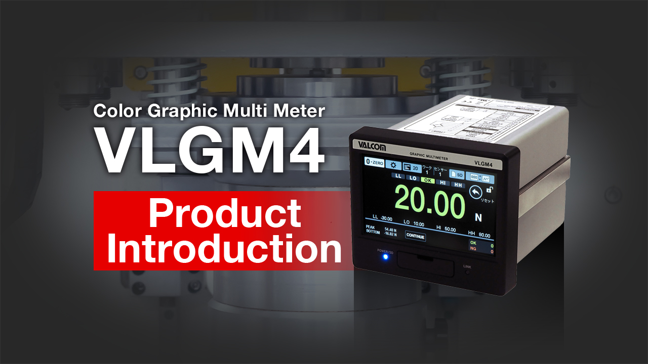
Color Graphic Multi Meter
(Strain Gauge and Displacement Sensor Inputs)
VLGM4 series
VLGM4-GP-RA-4 (D/A OUTPUT, RS-232C)
VLGM4-GP-RAE-4 (![]() )
)
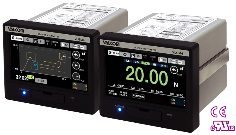
The VLGM4 displays measurement results on the shop floor in intuitively understandable colors, allowing users to quickly identify the current machine states or any errors detected. Various judgment functions include continuous, band, multi-zone, and combination, supporting all measurements such as pressure, load, and torque. This is the best graphic multimeter of its kind on the market.
NEW
Communication option
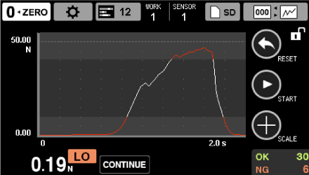
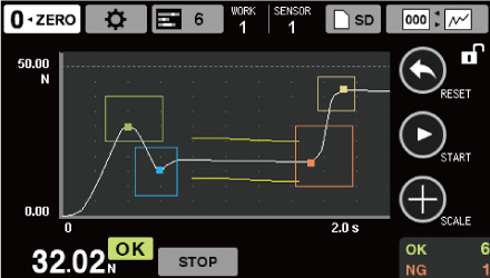
Real-time Waveform Graph and Judgment Functions Included
Sampling rate Max. 25,000 times/sec and Max. 5000 times/sec
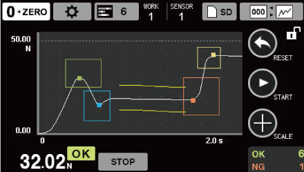
The VLGM4 is a highly functional multimeter and presents press fit and caulking loads that change chronologically on waveform graphs in real time. It also outputs error/control signals in case the preset higher/lower limits have been exceeded, and records judgment results, supporting traceability, quality control, and IoT manufacturing.


-
 Color display screen
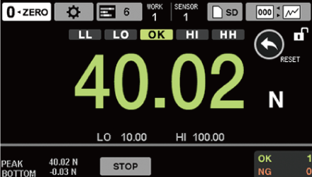
Clear and easy-to-read color LCD shows measurement results and safe/hazardous conditions on intuitively understandable interface.
-
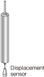
 Displacement sensor input
2 displacement inputs (voltage and pulse) adopted.
Support for pulse input (A/B phase or A phase, differential square wave (RS-422)) and voltage input ±5.2 V.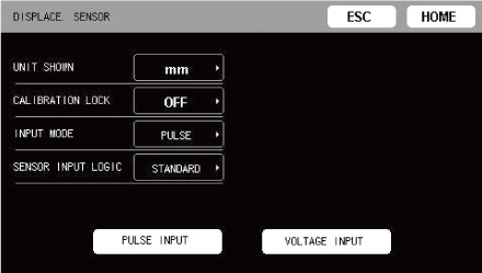
-
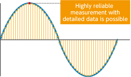
 High-speed sampling
Comparative judgment and detailed data sampling are available for systems running at faster cycle time, allowing users to choose 25,000 times/s or 5,000 times/s. (Resolution: 24-bit)
-
 TEDS function
(Transducer Electronic Data Sheet)At power on, sensor information is loaded to perform automatic calibration. The sensor information can be viewed and updated.
* This function is available for use in combination with the TEDS-compatible sensors.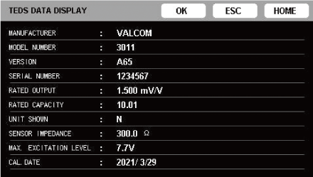
-
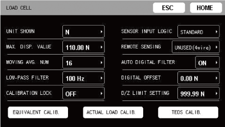
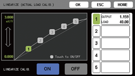
 Linearization calibration
(Adjustment function)The linearity of load measurements is improved by increasing the calibration points. This enables outputs close to characteristics values with less error. (5 points can be set.)
-
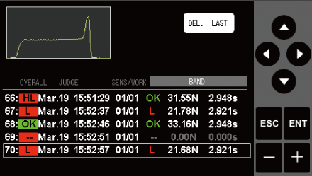
 Judgment result display function
The data you care about can be checked on the spot with the judgment result.

-
 Data saving
Internal memory
As well as measurement data, setting information and judgment results can be saved in CSV format (up to 70 files), making it easy to verify and utilize the results.
Measurement data: 70 (Lists and waveform can be confirmed & statistics can be displayed)
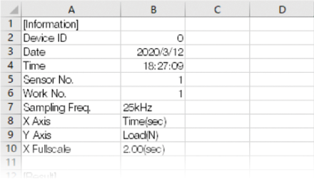
Files are saved in CSV format.
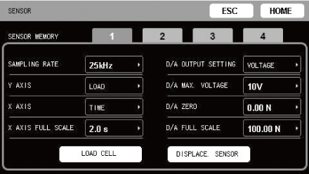
The unit can save 4 sets of settings for connected sensors.
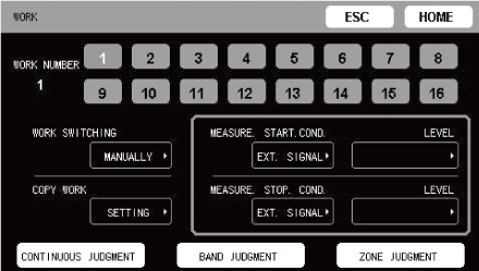
Up to 16 sets of measurement condition can be saved as works.
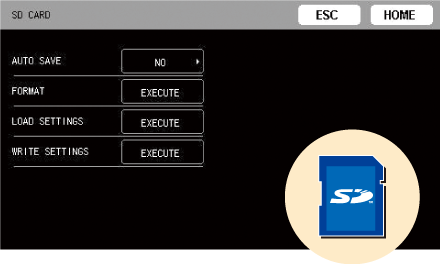
SD card
Measurement data can be saved on SD/SDHC cards as CSV or screenshot (image) files.
The VLGM4DataViewer (free software) allows the data to be organized and processed. -
 Data output
Analog output
The D/A converter allows for analog output that corresponds to the unit indicator value.
Voltage output: 0 - ±10V, Current output: 4 - 20mA
The maximum voltage output can be set between ±1V and ±10V in 1V steps using the D/A max. voltage setting.Digital output
Standard feature: RS-232C, USB * RS-232C and USB cannot be used at the same time.
Options: EtherNet/IP™ (Coming soon: CC-Link) -
 Various judgments
-
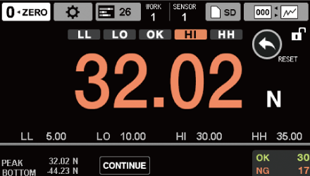
Continuous judgment
Determines whether it is OK or not by comparing the values being measured with the comparison values of "high limit, high high limit, low limit, and low low limit." In addition to digital display, this unit also supports graph display.
-
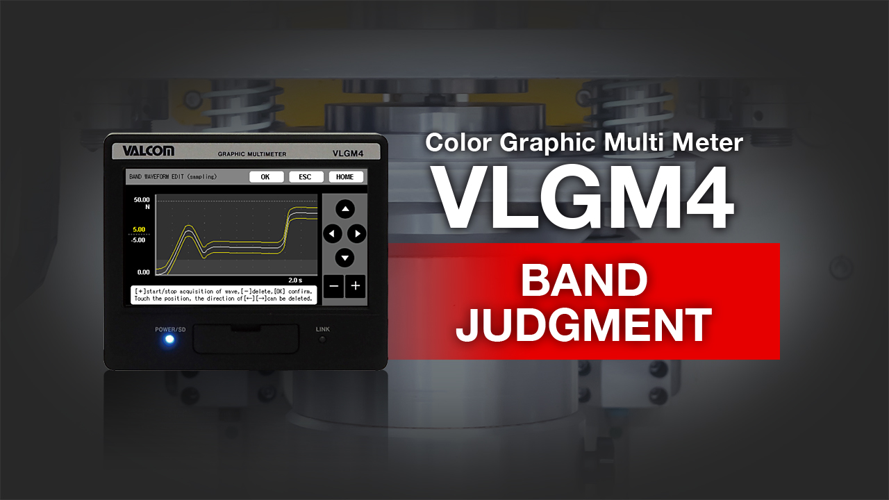
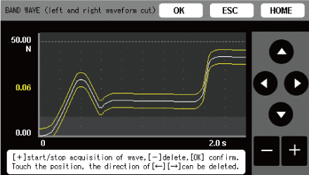
Band judgment
Continuously compares and judges measured values that change with time and displacement using the permissible band. Any curved line can be used for comparison.
-
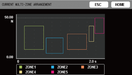
Multi-zone judgment
Determines whether or not the measured values are OK for the zones surrounded by the sections of allowable load and time or displacement. OK/NG is judged in a maximum of 5 zones for one process.
-
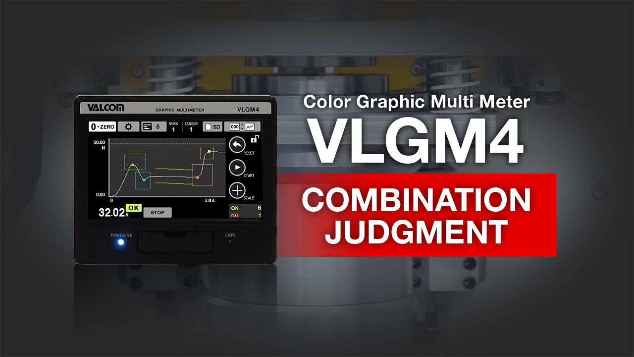
Combination Judgment
Determines OK or not for one work by combining "Band judgment" and "Multi-zone judgment." This enables detailed judgment even with complicated waveforms.
-
-
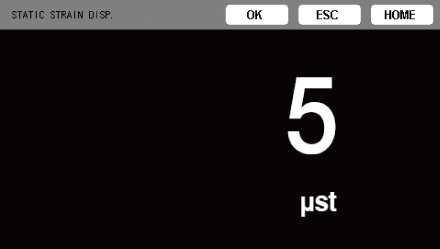
 Diagnostic Functions:
Static strain displayCan investigate defects such as load cell deterioration and plastic deformation. The input signal is displayed in strain amount unit (µST).
-
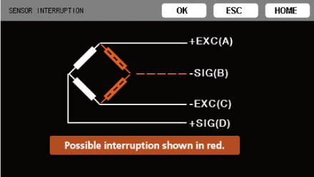
 Diagnostic Functions:
Disconnection detectionThe disconnection point of the load cell can be checked in real time. Detected location of the possible interruption will be shown in red.
-
Other diagnostic function
- Input/output terminal check function
- The status of control input/output signals on the back of the main unit can be checked.
- Input terminal
- Depending on the input signal, LOW (ON with yellow indicator) or HIGH (OFF) is shown.
- Output terminal
- Output can be turned ON/OFF for the connectors as desired. Use this when checking output connections.
-
 4 languages supported
The display language can be selected from among English, Japanese, Chinese and Korean, supporting overseas use such as on-site calibration.
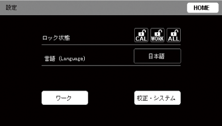
Language setting screen (Japanese)
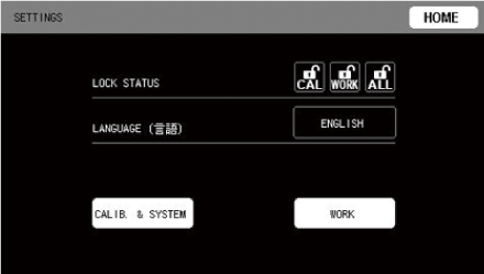
Language setting screen (English)
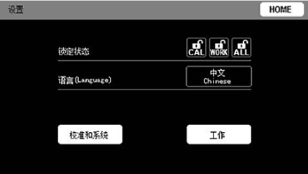
Language setting screen (Chinese)
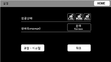
Language setting screen (Korean)
Free software
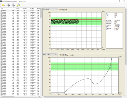
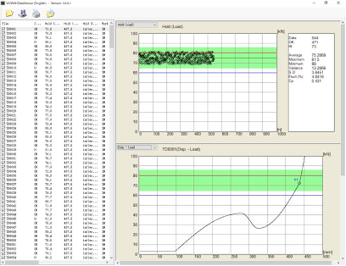
Offline data viewer program
VLGM4 DataViewer
This software displays and statistically analyzes the data recorded on the SD/SDHC card on a personal computer. It shows its true ability in statistical process control. Not only individual measurement data, but also trends and histograms of OK/NG judgment points for the entire list and statistically calculated values are displayed.
Recommended hardware
| CPU | 2nd generation Intel® Core™ i5, 3.0 GHz or faster |
|---|---|
| OS | Windows 8.1(32/64bit) Windows 10(32/64bit) |
| Memory | 4GB or more |
| HDD free space | 10GB or more |
| Screen resolution | 1024×768 pixels or higher .Net Framework 4 Client Profile |
* User registration required.
External dimensions
[Unit: mm]
Communication options
EtherNet/IP™, CC-Link (Coming soon)
A lineup of EtherNet/IP™ and CC-Link compatible models tha can be directly connected to a PLC.
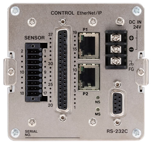
* Photo above is the EtherNet/IP™ model.
Basic specifications
| Model | VLGM4-GP-RA-4 | ||
|---|---|---|---|
| Load | Bridge Voltage | DC, 2.5/5/10 V, ±10% (30mA current maximum, can be used with remote sensing) | |
| Signal input range | ±3.2mV/V | ||
| Equivalent input/ TEDS |
Calibration range | 0.1mV/V to 3.2mV/V | |
| Calibration precision | Within 0.1% F.S. (when using 1m standard 8, 4-core shielded cable with 350Ω impedance, 10V BV and 3.2mV/V setting) | ||
| Precision | Linearity | Within 0.01% F.S. +1 digit (when input is 3.2 mV/V) | |
| Zero drift | Within 0.5 µV/°C (input conversion value) | ||
| Gain drift | Within ±0.005% F.S./°C | ||
| A/D conversion | 24-bit, 5000 times/second, 25000 times/second | ||
| Digital filter | Select 3, 10, 30, 100, 300, 1000 Hz(−6 dB/oct) or Off | ||
| D/A output | Output with same frequency as A/D conversion, isolated output, 1‒ 10V output (set in 1V steps) and about 1/59000 resolution (when set to 10 V), or 4‒20mA current output and about 1/43000 resolution | ||
| TEDS function | IEEE1451.4 class 2 mix mode interface | ||
| Displacement | Pulse | Pulse type | A/B phase or A phase, differential square wave (RS-422 conformance) |
| Maximum input frequency | 2MHz | ||
| Maximum count number | 15000000 | ||
| Power output | +5V±10%, 500mA | ||
| Voltage | Input | ±5.2V | |
| Low-pass filter | Off/10/30/100/300Hz | ||
| Power output | DC12V±10%, 250mA | ||
| Display | 4.3" color LCD (480×272) | ||
| Indicator value | Display range | −32000 to 32000 | |
| Decimal point | Display position selectable | ||
| Times displayed | 4 times/second | ||
| External input and output signals | Input | Differential pulse position sensor (A phase, B phase), force backlight lighting, prevent touchscreen operation, force reset, work switching (4-bit), switch zone, clear results (reset measurement results), enable/disable judgment output, start/stop measurement, zero balance displacement, digital zero Isolated from main unit circuits using a photocoupler | |
| Output | Load judgment output (HH, HI, OK, LO, LL), displacement judgment output (HI, OK, LO), load cell error, measurement complete, trigger output (1, 2) Open collector output (isolated from main unit circuits using a photocoupler) |
||
| RS-232C | RXD, TXD | ||
| SD card slot | Applicable media: SD/SDHC Storage capacity: 2~32 GB Speed class: Class 10 recommended |
||
| Power supply | Ratings: 24V DC ±10%, 13W AC100-240V: PA-91 (AC adapter is optional) |
||
| Operating temperature range | 0 to 40°C | ||
| Storage temperature range | −20 to 60°C | ||
| Operating humidity range | 85% RH or less (without condensation) | ||
| Applicable standards | CE marking, FCC (Class A), UL61010-1 | ||
| External dimensions (W×H×D) | Approximately 114mm×96mm×140mm (without protrusions) | ||
| Weight | About 960g | ||
| Option | Ethernet/IP™ (Model: VLGM4-GP-RAE-4) | ||
| Accessories | Sensor connector plug, control connector plug, power terminal block cover (premounted), instruction manual | ||
* Specifications and appearance are subject to change without notice.
* Illustrations in this owner’s manual might differ slightly from production models.
- * 株式会社バルコム are resistered trademark of Valcom Co., Ltd in Japan, Taiwan , China and Korea.
- * VALOCOM are resistered trademark of Valcom Co., Ltd in Japan, Taiwan and China.
- * CC-Link is a registered trademark of Mitsubishi Electric Corporation.
- * EtherNet/IP™ is a trademark of ODVA, Inc.
- * SD and SDHC logos are trademarks of SD-3C and LLC.