![]() Arithmetic Function (2-channel Input)
Arithmetic Function (2-channel Input)
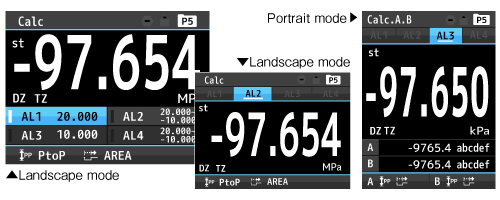
Measured values for each channel simultaneously show 1~3 results of arithmetic operations that can be chosen from 10 formulas respectively.
Specialized manufacturer of Digital Pressure Meters and Load Cells
![]()
Multifunctionality and Various Display Modes to Step into a New Realm
Process input
A/Bch
VGM5-1
Straingauge input A/Bch
Process input A/Bch
VGM5-3
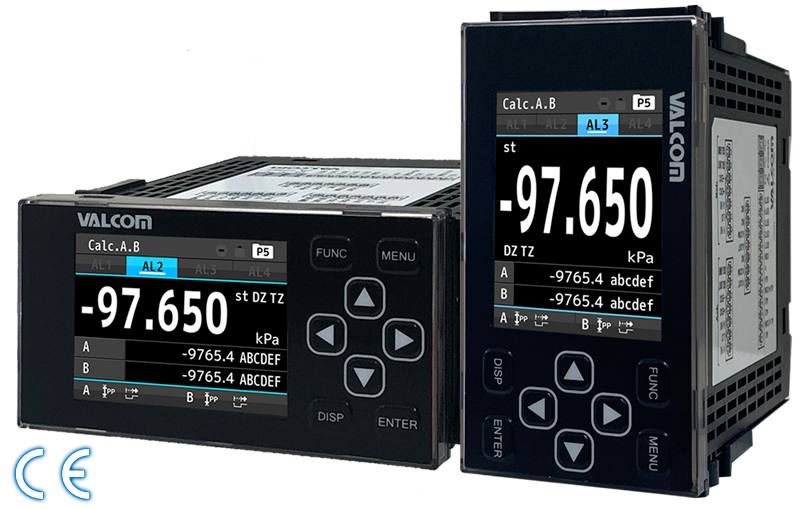
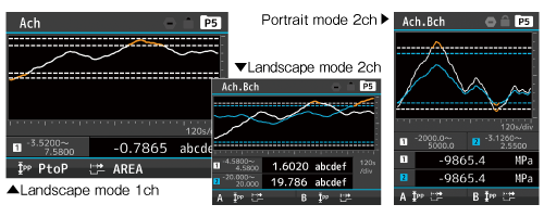
Graphical presentation with bar and trend graphs, portrait and landscape modes of screen orientation, and intuitive status indication with 3 colors (R/Y/G). VGM5 series, full of these features required on site, creates a new realm of panel meters.
Two models: VGM5-1 and VGM5-3 are available. The former enables 2-channel (A/B) process input, and the latter supports 2-channel (A/B) strain gauge and process inputs.
VGM5-3 flexibly supports measurement system from load cell (strain gauge).
Besides multiple input, the VGM5 series supports graphs, waveforms, and color presentation on a large and clear display that can be set in portrait and landscape orientations.
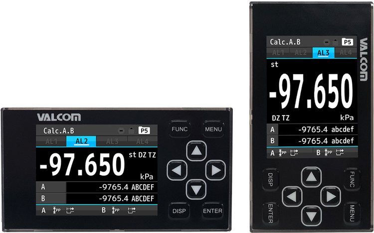
![]() Display Rotation Function
Display Rotation Function
Standard feature includes the rotation of the screen by 90 degrees. You can choose between landscape and portrait modes. For example, addition of digital panel meter that was unexpected at the system development stage, can become another option.
Orientation selectable to
suit the on-site needs
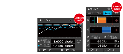
![]() Trend (Line Graph) Display
Trend (Line Graph) Display
This graph allows you to grasp the trend in measurement (for example, any problem in press-fit or variations in multiple press).
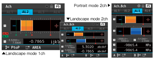
![]() Level (Bar Graph) Display
Level (Bar Graph) Display
Shows the percentage of the measured value in the whole, allowing it to be expressed relatively.
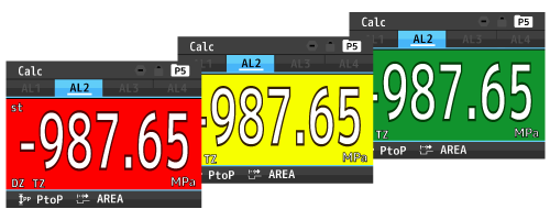
![]() Easy-to-Identify Color Presentation
Easy-to-Identify Color Presentation
Background color that changes automatically when outputting alarms is selectable from red, yellow and green. Highly identifiable universal color design adopted.
![]() Arithmetic Function (2-channel Input)
Arithmetic Function (2-channel Input)
Measured values for each channel simultaneously show 1~3 results of arithmetic operations that can be chosen from 10 formulas respectively.
Formulas available for 2-channel input arithmetic function
| Arithmetic operation | Calculation formula |
|---|---|
| Addition | ((A+B)+C)×K |
| Subtraction | ((B−A)+C)×K |
| Multiplication | ((A×B)+C)×K |
| Division | ((B/A)+C)×K |
| Average | (((A+B)/2)+C)×K |
| High selector | ((A or B, whichever is greater)+C)×K |
| Low selector | ((A or B, whichever is smaller)+C)×K |
| Absolute difference | ((Absolute value of the difference (B−A))+C)×K |
| Error ratio | ((A/B)−1)×K |
| Concentration | (B/(A+B))×K |
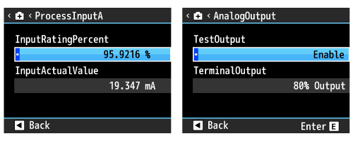
![]() Self-diagnosis Function
Self-diagnosis Function
This function is incorporated in order to prevent possible accidents with the connected equipment. It enables you to confirm safety before starting operation or inspection.
![]() Waveform Comparison Function [VGM5-3 only]
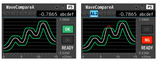
Waveform Comparison Function [VGM5-3 only]
Alarm output and waveform log are enabled by comparing measured waveform and reference waveform. (2-channel simultaneous comparison available)
![]() Multi-Hold Mode [VGM5-3 only]
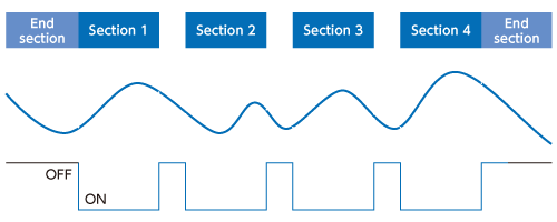
Multi-Hold Mode [VGM5-3 only]
Comparative output is made by comparing the hold value and the preset reference value for each section. This enables judgment section by section in caulking process, etc.
![]() Wealth of Optional Functions
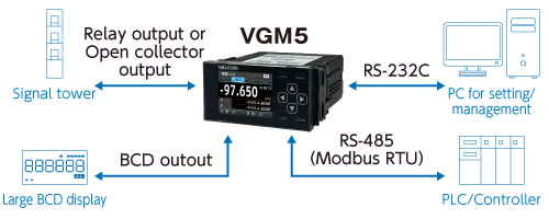
Wealth of Optional Functions
Communication/output functions are available from RS-485 (Modbus RTU), RS-232C, analog output and BCD output.
![]() Language Switching (English/Japanese)
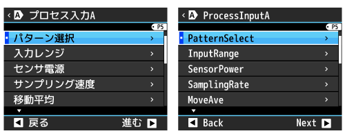
Language Switching (English/Japanese)
Display language can be easily switched between English and Japanese in the Language setting menu.
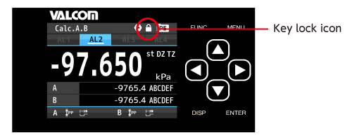
![]() Key Lock Function
Key Lock Function
This function disables buttons to prevent possible accidents due to careless operation.
| Number of input channel | 1 or 2 (According to model codes) | ||||||
|---|---|---|---|---|---|---|---|
| Display | 2.4 inch TFT liquid crystal display Used in 1ch input: A ch. measurement result Used in 2ch inputs: A ch. measurement result, B ch. measurement result, calculation result, A ch. and B ch. measurement results, A ch. or B ch. measurement result and calculation result |
||||||
| Over warning | By exceeding the range of display, displays OVER or − OVER | ||||||
| External controls |
|
||||||
| Ambient temperature range | −5 to 50°C, 35 to 85%RH(Non condensing) | ||||||
| Storage temperature range | −10 to 70°C up to 60%RH | ||||||
| Supply power |
|
||||||
| Power consumption |
|
||||||
| External dimension's | 96mm(W)×52mm(H)×145mm(D) | ||||||
| Weight | Approx. 350g | ||||||
| Withstand voltage |
|
||||||
| Insulation resistance | Between terminals mentioned above, at DC500V 100MΩ or higher | ||||||
| Vibration tolerance | 10 to 55Hz half amplitude 0.15mm in X, Y, Z directions for 30 minutes | ||||||
| Protective structure | IP66(front) | ||||||
| Installation environment | indoor use | ||||||
| Rated altitude | up to 2000m | ||||||
| Transient overvoltage | II | ||||||
| Pollution degree | 2 | ||||||
| Conformed EN standard | EN61326-1(EMS: industrial electromagnetic environment/EMI: Class A) (Applicable to line length only under 30m) EN61010-1, EN50581 |
||||||
| Material of enclosure | polycarbonate(PC), black UL94V-0 |
| Measurement range | ±5V, 0 to 5V, 1 to 5V, ±10V, 0 to 10V, ±20mA, 0 to 20mA, 4 to 20mA |
|---|---|
| Input resistance | Approx. 1MΩ(±5V, 0 to 5V, 1 to 5V, ±10V, 0 to 10V) Approx. 10Ω(±20mA, 0 to 20mA, 4 to 20mA) |
| Maximum arrowable input | ±100V(±5V, 0 to 5V, 1 to 5V, ±10V, 0 to 10V) ±50mA(±20mA, 0 to 20mA, 4 to 20mA) |
| Accuracy (at 23±5°C 35 to 85%RH) |
±(0.05% of FS+1digit) |
* It is possible to measure up to ±10% FS range on each range. (Limited with ±10% FS by internal processing.)
In the bipolar input setting, the full scale is set to be ±separately, and for ±10V input, for example, limit processing is performed up to ±11V. (20V is not treated as FS.)
Also, in the accuracy of ±10V input, it is prescribed as one side FS handling and accuracy is calculated as 5mV (0.05%) ±1 digit.
| Conversion method | ΔΣconversion method |
|---|---|
| Input signal | Single ended |
| Sampling rate | Max. 4000times/sec (1ch product) Max. 2000times/sec (2ch product) |
| Display updating period | 10sps, 1sps |
| Display resolution | 1/99999 |
| Zero display | Reading zero suppress |
| Decimal point | Settable freely |
| Display range | −99999 to 99999 |
| Sensor power supply | DC12V±10% 100mA max./DC24V±10% 50mA max. * Allowable current of 2 ch input is the above current together with A ch. and B ch. * When used with a combination of DC12V and DC24V, power consumption is 1.2W max. * When used in combination with strain gauge input, power consumption is 1.2W max in total. (VGM5-3 only) |
| Bridge power supply | 5V, 10V, 2.5V |
|---|---|
| Adjustment range of gain | 1mV/V to 3.5mV/V |
| Measurement range | −3.5mV/V to 3.5mV/V |
| Calibration accuracy (at 23±5°C 35 to 85%RH) |
±(0.1% of FS+1digit) |
| Nonlinearity (at 23±5°C 35 to 85%RH) |
±(0.02% of FS+1digit) |
| Conversion method | ΔΣconversion method |
| Applicable bridge resistance | 350Ω |
| Bridge voltage | DC5V±10% 60mA * Four 350Ω load cells can be connected DC10V±10% 30mA DC2.5V±10% 30mA * When used in combination with process input, please use up to 1.2W in combination with the power consumption of the sensor power supply. |
| Temperature characteristic | 100ppm/°C |
| Input signal | Single ended |
| Sampling rate | Max. 4000times/sec (1ch product), Max. 2000times/sec (2ch product) |
| Display updating period | 10sps, 1sps |
| Display resolution | 1/99999 |
| Zero display | Leading zero suppress |
| Decimal point | Settable freely |
| Display range | −99999 to 99999 |
| Open collector output | [Output rating] NPN: Sink current 50mA MAX. / PNP: Source current 50mA MAX [Applied voltage] 30V MAX. [Output saturation voltage] ≤ 1.2V at 50mA [Number of outputs] 4 transistor outputs |
||||||||||||||||||||||||||||||||||||||||||||||||||
|---|---|---|---|---|---|---|---|---|---|---|---|---|---|---|---|---|---|---|---|---|---|---|---|---|---|---|---|---|---|---|---|---|---|---|---|---|---|---|---|---|---|---|---|---|---|---|---|---|---|---|---|
| Relay output | [Contact rating] AC250V 2A, DC30V 2A [Mechanical life] 20 million times [Electrical life] 100 thousand times or more 4 A contacts, AL1 and AL2, AL3 and AL4 share common |
||||||||||||||||||||||||||||||||||||||||||||||||||
| Control method | Microcomputer calculating method | ||||||||||||||||||||||||||||||||||||||||||||||||||
| Judgement value settable range | −99999 to 99999 | ||||||||||||||||||||||||||||||||||||||||||||||||||
| Hysteresis | Settable within the range of 1-99999 digits for each judgement value independently | ||||||||||||||||||||||||||||||||||||||||||||||||||
| Comparison action | According to sampling rate (circulate period). | ||||||||||||||||||||||||||||||||||||||||||||||||||
| Setting condition | Condition of comparison can be set to AL1 to AL4 independently Level judgement modeThe alarm is ON when display value exceeds judgement value (over alarm) Over alarm (upper limit judgement)
Under alarm (lower limit judgement)
Zone judgement modeThe alarm is ON when display value between upper and lower judgement values (inside of zone alarm) Inside of zone alarm
Outside of zone alarm
Difference judgement modeWhen the (maximum - minimum) during the fixed time exceeds the judgement value, alarm ON
|
||||||||||||||||||||||||||||||||||||||||||||||||||
| Comparison formula memory | 8 pattern memory |
| Conversion method | D/A conversion method |
|---|---|
| Resolution capability | Equivalent of 13bit |
| Scaling | Digital scaling |
| Output objective | An item can be selected from source displayable values |
| Circuit response | Up to 300µs (0→90% response) |
| Output type | 0 to 10V, −10V to 10V, 1 to 5V, 0 to 20mA, 4 to 20mA |
| Load resistance | ≥2kΩ(0 to 10V, −10V to 10V, 1 to 5V), ≤550Ω(0 to 20mA, 4 to 20mA) |
| Accuracy (23±5°C 35 to 85%RH) |
±(0.1% of FS) |
| Ripple | ±50mVp-p(0 to 10V, −10V to 10V, 1 to 5V) ±25mVp-p(0 to 20mA, 4 to 20mA) *Ripple is at load resistance 250Ω, 20mA output. |
| Output type | Open collector output NPN/PNP type |
|---|---|
| Measurement data | Negative logic transistor is ON at logical "1" |
| Polarity signal | Negative logic transistor is ON at minus display |
| Over signal | Negative logic transistor is ON at over display |
| Synchronized signal (PC) | Transistor is ON for a fixed period every time data becomes valid. |
| Transistor output capability | Voltage 30V max. Current 10mA max. Output saturation voltage up to 1.2V at 10mA |
| Enable | By shorting the enable terminal to −D.COM or bringing to same voltage level, the BCD output transistors become OFF. |
| Communication protocol | Modbus-RTU, OriginalCommand, OriginalOutput |
|---|---|
| Synchronization method | Asynchronous |
| Communication method | Full duplex |
| Baud rate | 9600bps, 19200bps, 38400bps |
| Data length | 7bit, 8bit |
| Start bit | 1bit |
| Parity bit | None, Odd, Even |
| Stop bit | 1bit, 2bit |
| Delimiter | CR LF, CR |
| Character code | Code ASCII |
| Transmission control procedure | No control sequence |
| Used signal names | TXD, RXD, SG |
| Number of connectable units | 1 |
| Cable length | Max. 15m |
| Communication protocol | Modbus RTU |
|---|---|
| Synchronization method | Asynchronous |
| Communication method | 2-wire half- duplex |
| Baud rate | 9600bps, 19200bps, 38400bps |
| Data length | 8bit |
| Start bit | 1bit |
| Parity bit | None, Odd, Even |
| Stop bit | 1bit |
| Used signal names : | Non-inverting (+), Inverting (−) |
| Number of connectable units | 31 |
| Cable length | Max.1.2km (total) *Conforming CE mark, less than 30m |
①Model
①
②Supply power
②
③Input Ach.
③
④Input Bch.
④
⑤Output
⑤
⑥Comparative
output
⑥
⑦Test report
⑦
⑧Additional
code
⑧
| Selection | Cheak | Model | Specifications |
|---|---|---|---|
| ①Model | VGM5-1 | DC Voltage / DC Current measurement | |
| VGM5-3 | Straingauge meter, DC Voltage / DC Current measurement | ||
| ②Supply power | 7 | Supply power: AC100 to 240V | |
| 5 | Supply power: DC12V | ||
| 8 | Supply power: DC24 to 48V | ||
| ③Input Ach. | N | Process input | |
| GV | Straingauge input *Only VGM5-3 can be selected. | ||
| ④Input Bch. | X | No B ch. input | |
| N | Process input | ||
| GV | Straingauge input *Only VGM5-3 can be selected. | ||
| ⑤Output | D | Display only (No output) | |
| A | Analog output | ||
| B4 | BCD output (open collector NPN) | ||
| B5 | BCD output (open collector PNP) | ||
| RS | RS-232C | ||
| R2 | RS-485(Modbus RTU) | ||
| ⑥Comparative output | ON | Open collector NPN | |
| OP | Open collector PNP | ||
| SA | Relay output (Normally open) | ||
| ⑦Test report | X | Without test report | |
| T | With test report | ||
| ⑧Additional code | 00 | Standard (Initial language: Japanese) | |
| E0 | Initial language setting: English |
The VGM5-3 series supports both process input and strain gauge input, adding another step toward broader measurement range.
Differential pressure control for two-part adhesive dispensing system
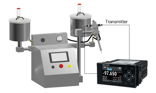
Recommended pressure sensors
VPRF, VF, VFM, VESIM□□A
For Press fit machines
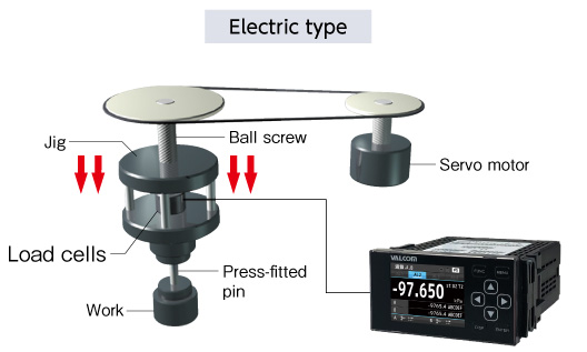
Recommended load cell
VLC-E344, VLC-H400, VLC-G811, VLC-G510A, VU93
For Hydraulic press machines
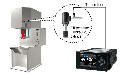
Recommended pressure sensors
VESV/VESI, VPVT(F)/VPVQ(F)
Hydraulic control for Coating machines or dispensers
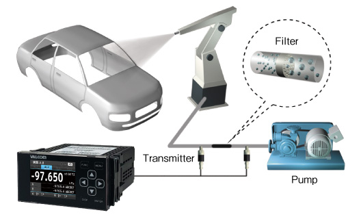
Recommended pressure sensors
VPRF, VF, VFM, VESIM□□A
Membership is required to use the download service.
If you have already finished registration, log in from here.
If not yet, click here to register for membership.